Arduino based environment logging
Last updated: May 25, 2012, 6:34 p.m.
A week ago now I was part of a team from Bristol Hackspace who went to Devon to provide a "pop up hackspace" for the FSC Hackday event. The weekend was a lot of fun and in between helping people with their hacks I had a bit of time to work on some of my own. The most complete build was an environment data logger. I was just logging temperature but you could always hook up other sensors.
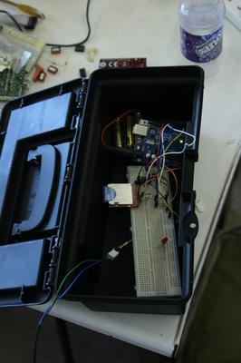
The build consisted of four main components and some bits of breadboard and resistors etc.
Arduino UNO
The centre of the logger was a standard Arduino. I hooked up the power to a pack of six AA batteries to make sure it had enough power to log for a long time because I didn't have any power saving features in my code. The sketch is in the GitHub repository.
DS1307 Real Time Clock
To keep track of real world time I used the DS1307 real time clock. I didn't have a separate battery for the clock so the Vbatt input was connected to GND, and I had to leave the power on all the time after I'd set the clock so it didn't get set wrong. I used the code example and library from Adafruit, there's a line commented out in this code that compiles the current clock time on your PC into the image in the Arduino and sets the RTC to that time if it isn't running. When you disconnect the power to the real time clock it sets a flag bit to tell the micro-controller that it doesn't have accurate time. This means that so long as you keep power to the Arduino and clock from the point at which you program it, the clock will only be a few seconds out (the delay between compiling and the processor starting to run).
SD Card
I used an SD card to log the data. The SD datalogger example in the IDE is the basis for the code. The SD card socket we were using was the basic breakout board from SparkFun, this is just an SD socket to 0.1" header adapter and has no level shifting or power regulators in it. SD cards run at 3.3V so it was powered off the 3.3V output of the Arduino and the MOSI, SCK and CS lines which are outputs on the Arduino were run through simple potential dividers with a 1.5k and 3.3k resistor.
Sensor
I was logging temperature using a Dallas DS18B20 precision one-wire digital temperature sensor. I didn't use the one-wire mode, it was powered from a separate power wire. I grabbed the OneWire library from the Arduino Playground and based my code on one of the examples that came with it.
Output
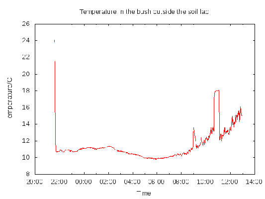
To test the whole setup I put the whole prototype in a toolbox and shoved it under a bush for the night. The output was a reasonable graph of the overnight temperature. The spike at the left is the temperature of the room I was finishing the coding in. The two spikes in temperature the next morning are two occasions I took the unit inside to get the data out of it. Once you've removed the SD card you need to replace it then press the reset button on the Arduino (DON'T TURN IT OFF!!) to re-initialise the SD card. All the lines of data have the time at the start of them so you don't need to worry about missing samples.
Schematics and Code
All the schematics and code for the project are in a GitHub repository, you can pull the lot or just download the bits you want. The schematic was done in KiCAD.
Comments
Posting comments is not currently possible. If you want to discuss this article you can reach me on twitter or via email.

