H-Bridge Tutorial
Last updated: Jan. 25, 2012, 8:21 p.m.

The H-bridge is a circuit used in electronic control of high current devices, particularly where the device polarity may be reversed, e.g. DC motors. The name comes from the fact that the circuit typically looks like a letter "H".
Full bridge operation

The circuit shown has four switches and a motor. To apply a voltage across the motor a pair of diagonally opposite switches need to be turned on. Depending on which pair of switches are turned on the motor will turn one way or another. If both the top or both the bottom switches are turned on the motor will have no voltage difference across it so it won't move at all. If the top and bottom switches on one side are turned on together by accident we will short out the supply, so you need to be careful if you're building your own H-bridge. Most pre-packaged ones will have internal logic to prevent this.

You can build an H-bridge like this out of relays instead of switches and control them with a lower current to drive big motors but most often the switches are replaced with transistors, a pair of PNP transistors (or p-type MOSFETS) at the top and a pair of NPN (or n-type MOSFETS) at the bottom.
PWM Control of a full bridge
PWM is a method of digitally controlling an output with a variable equivalent voltage. Essentially if you take the average of the signal over time then it has a varying analog level, however in the short term it is digital. This makes it easy to generate and efficient as transistors are most efficient when on or off rather than partially conducting. Most modern microcontrollers have the ability to generate PWM built in, including the Arduino and derivatives.
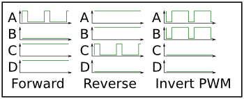
To control a plain H-bridge you need 4 signals to control the 4 transistors, to control it with PWM you need two PWM signals and two plain digital signals. You could theoretically use just the two PWM outputs, however you need to be careful about the polarity of the signal compared to the transistor you're driving. Some microcontrollers include a full bridge driver (Microchip call this Enhanced Capture/Compare/PWM or ECCP on their 8bit PIC chips) which drives 4 outputs and you can hook up to the H-bridge. However it still needs 4 control lines. If you can drive both your PNP and NPN transistors from the same logic line (i.e. your motor power and logic rails are the same) you can connect the PWM to both A and B inputs and a direction control to C and D. In this configuration however you have to invert the duty-cycle when you are running in reverse because it's the low part of the duty cycle that turns the motor on, shown as "Inverted PWM" above.
Better PWM control

There are a couple of ways I can think of to make the H-bridge much simpler to control. Essentially what we want is to add an over-all enable line to the H-bridge so we can use one enable line controlled by PWM rather than using a complex H-bridge driver. One way is to add another transistor to the circuit that only connects the bottom rail of the H-bridge to the negative supply. Pulsing this will make the motor run only while the control is high so PWM on this would make an overall speed control without having to worry about which direction the motor is running. The cost of the extra transistor could be quite high if you're using high power transistors or MOSFETS and depending on your voltage rails this might be eating into your motor voltage as there'll be a 0.7-0.4V drop across each transistor or MOSFET. The other option then is to use logic to filter the control lines so that the PWM signal is combined with the direction signals.

Using an H-bridge chip
In a lot of cases, especially with little toy motors, you don't need to build a whole H-bridge circuit from scratch. In fact using a chip can save you a lot of trouble with offset voltages; if you have a different motor supply voltage from your logic voltage you'll need drivers between the logic and the power transistors. There are a couple of chips I'd recommend and it depends really on how powerful your motors are which one to use, both are dual H-bridge chips (so you can control 2 motors) and both have 2 enable lines so you can connect a PWM line for each motor.
L298

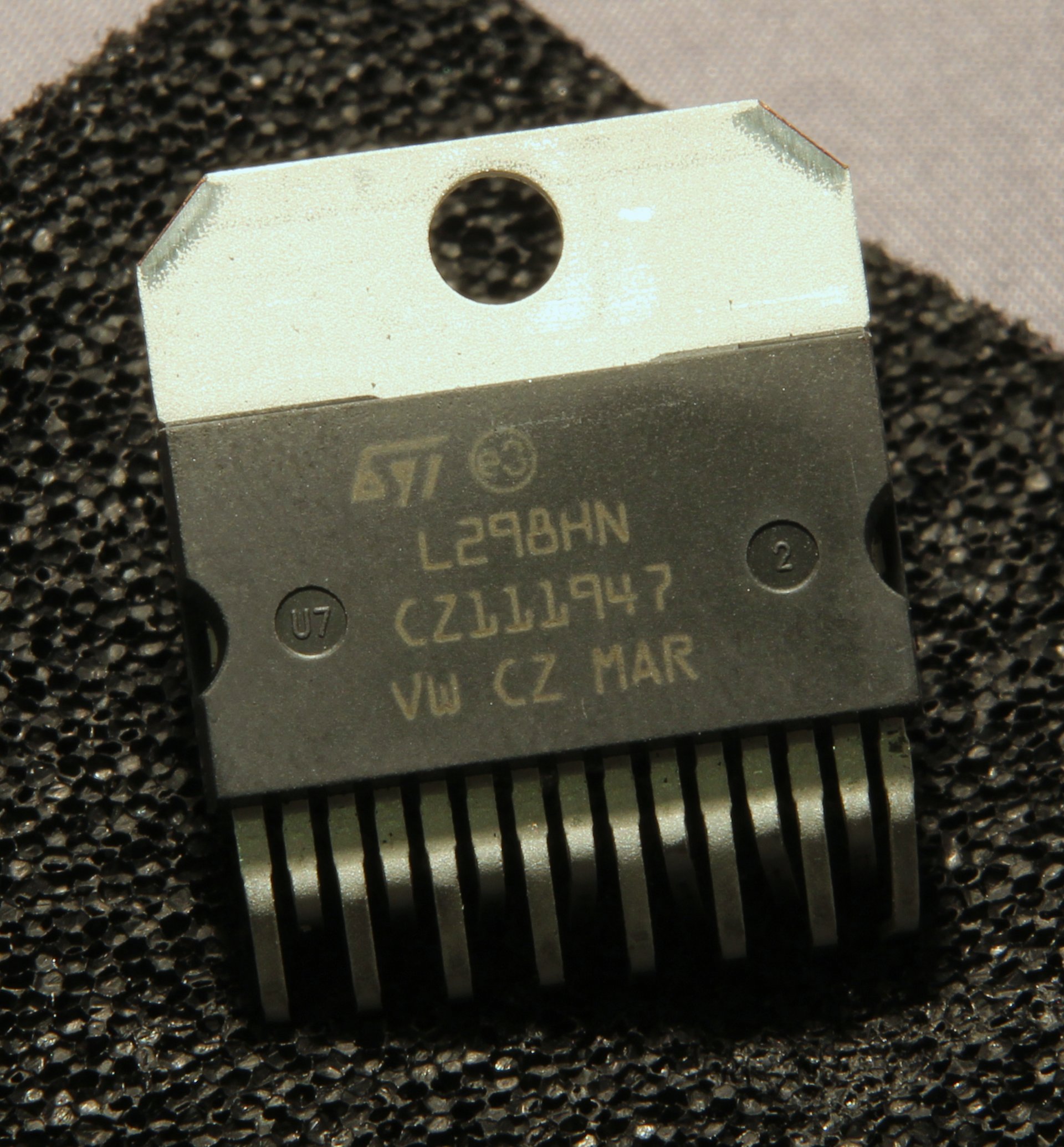
The 298 is a high power dual-H-bridge driver which can handle 2A continuous current on each channel. It's in a big heat-sinkable package and if you're running it close to the limit I'd recommend using this heat sink. The 298 also has current sense lines on each of the two channels which you can add a low value resistor to ground and monitor the current being drawn by each motor. If you need to save some pins you can bridge the direction lines with a not gate and only use one line for direction control. Yu can also parallel up the inputs and outputs on this chip to make a 4A continuous drive bridge but you need to be careful to wire up the inputs in the right order. You need to provide your own protection diodes to suppress the inductive response of the motor and protect your circuit from negative voltages, these are wired "backwards" across your motor supply.

L293/SN754410

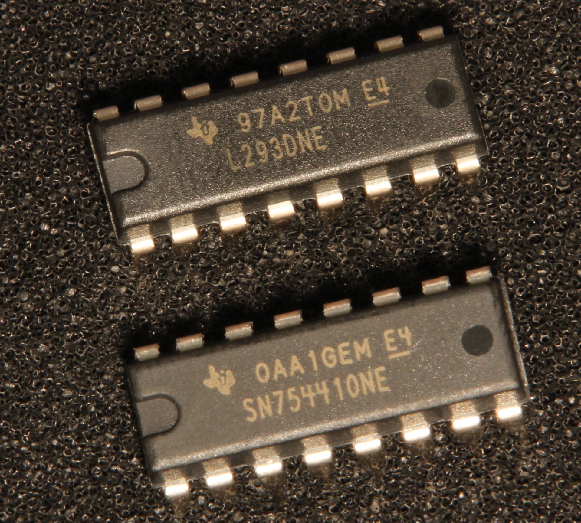
The L293 (and pin compatible SN754410) have a very similar block diagram to the L298 but a much lower current capacity. The continuous running current is 1A for the L293/SN754410 or 0.6A for the L293D. It is packaged as a normal DIP IC so if you need to heat sink it you're recommended to have a big ground plane connected rather than a heat sink block. This is fine if you have a PCB but it can be a bit difficult to achieve on strip board. The L293D can only handle about half the current of the L293 but has internal protection diodes so it really is a single component solution for driving low power motors. The SN754410 has the protection diodes for running inductive loads as well but can handle up to 1.1A continuous current, it has identical pinout and better absolute maximum ratings so is a safe drop in replacement for the L293D.
Arduino Shield
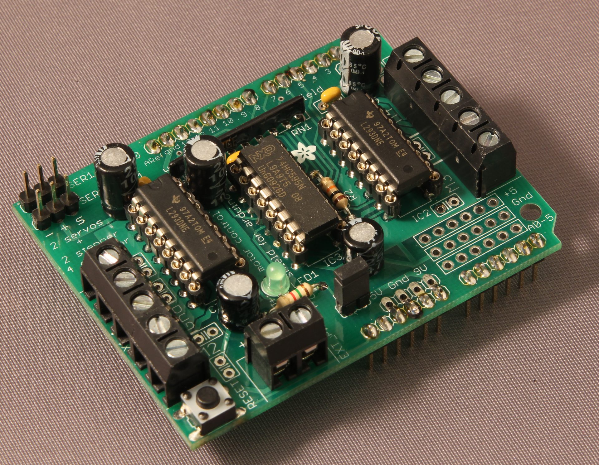
The Motor Shield by Adafruit includes a pair of L293D chips to drive up to four motors or a pair of stepper motors. The schematics and software are available from the downloads tab.
Datasheets
st.com L298 Farnell: 403-295 ti.com L293/L293D Farnell: 147-0423 ti.com SN754410NE Farnell: 147-0411
Comments
Thanks
18 Aug 2013 - 02:09 Juan
I was looking for this information and it was great to find it in one place. Thank you!
PWM control
27 Oct 2013 - 19:47 Nishant Kukreja
Can you please explain how speed of motor can be changed using this circuit. I am not able to visualize it properly.
Re: PWM control
31 Oct 2013 - 13:00 nathan
See the paragraph immediately after the title "PWM Control of a Full Bridge" for an explanation of how PWM works.
PWM control OR gate
28 Oct 2013 - 15:44 Nishant Kukreja
Can u please explain how pwm controls motor speed using or gate since above logic 0 voltage it always gives vcc?
Re: PWM control OR gate
31 Oct 2013 - 13:09 nathan
See the comment above for discussion of OR/AND logic. Essentially if the output of the PWM inverter is high then both sides will be driven high turning on only the lower transistors, shorting both sides of the motor to ground so not driving the motor. If the PWM inverter output is low (i.e. PWM is high or "on") then the OR gates function as simple buffers and the control of the H-Bridge is entirely dependent on the direction controls, so if DIR1 is high and DIR2 is low the motor will run one direction and if DIR1 is low and DIR2 is high the motor will run the opposite direction.
PWM control OR gate
31 Oct 2013 - 19:48 Nishant Kukreja
Sir I am asking about varying the speed of motor based on the PWM values since or gate will give high or low only and not pwm voltage
Re: PWM control OR gate
02 Nov 2013 - 12:36 nathan
PWM is only high or low, that's the whole point of PWM. It is a digital signal right the way through the h-bridge and is only "averaged" to an effective analog value in the motor. If the control voltage applied to the transistors was effectively analog then they would dissipate much more energy so the control signal has to be only high or low.
If you want to discuss this article you can reach me via email.
OR logic, instead AND
05 May 2012 - 17:05 boni
Hi, if I'm right, there sould be AND gate in the "logic controlled h bridge", not OR. I tried this circuit with AND logic in Yenka and it worked well.
OR logic instead of AND
06 May 2012 - 20:12 nathan
AND gates should work here as well, but you'll probably want to remove the inverter on the PWM line otherwise your duty cycle will be inverted. I used OR gates because I wanted the lower (N-channel) transistor to be on when the PWM line is inactive, rather than the upper transistor as will be the case with AND gates, in either case the motor won't be powered as there's no voltage drop across it.
Really you should drive the upper two transistors with the OR circuit with inverted PWM like I did, and the lower two transistors with AND gates and an un-inverted PWM so that when the PWM signal is low (inactive) all four transistors are off and the motor can free-wheel.