Nathan's Z80 Project Mark 2: CPU Supervisor
Last updated: Aug. 24, 2009, 10:43 p.m.
A large amount of the usual faff found in Z80 systems has been avoided in my design by including a PIC next to the Z80. This PIC replaces the reset timing circuit, the clock generation circuit for the Z80 and the need for ROM and associated decode logic to select the ROM chip. In addition it provides mass storage (via an SD card interface) and a useful in-circuit emulator for debugging.
All this is achieved by giving the PIC ultimate control over the Z80 by controlling the reset and clock lines, as well as the DMA control lines. The PIC can then control the system while the Z80 is in reset or DMA mode. Since PICs can turn their pins from input to output, several pins function both as input and output depending on what the PIC is doing (e.g. RD, WR, WAIT etc.) Others have been added specifically for debugging or booting (e.g. MREQ, IORQ, and address pins). To be able to drive the whole 16bit address bus the PIC uses a latch for the high 8bits. The lower 8 are driven directly by PortB, this allows for fast block transfers because the latch only needs to be updated once every 256 bytes, so sector transfers from a typical SD card with 512byte sectors only require the latch to be altered twice (at max) within the transfer.
The clock signal for the Z80 has to be a TTL compatible square-wave, this is produced by one of the PIC's PWM pins (CCP1). By setting it up for 50% duty cycle the output of the PWM peripheral can be set to run at several MHz, so quite adequate for an old Z80 chip. If the system was going to use one of the faster modern variants that can run at 16MHz this scheme would probably have to be replaced.
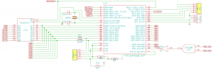
The ROM is replaced by the PICs internal FLASH memory. I'm using an 18F4520 with 32K of FLASH so a small (few kilobyte) ROM image can be accommodated easily in space within this internal memory. Upon reset the PIC holds the Z80's reset line low and proceeds to copy the data from it's own program memory into the start of the system RAM, once this is complete the reset line is brought high, and the PIC switches to peripheral mode, and awaits instructions from the Z80 or its debug UART interface. The plan is for the boot ROM to be a very small piece of code which is just enough for the Z80 to load a more complete kernel from the SD card, allowing alterations to the kernel to be made without re-programming any chips, just change a file on the card. This also puts the responsibility of providing hardware drivers at the feet of the operating system, not the system ROM. This means that only those needed can be loaded, saving space, and that the kernel could be ported to another platform more easily as the drivers are dynamically compiled in rather than calling ROM functions at fixed locations in memory.
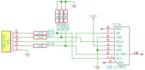
The SD card interface for mass storage is very simple, it simply hooks up the PIC's built-in SPI hardware to the SD card via a set of simple voltage dividers to match the 3.3V logic used in SD cards. The SPI interface is speed limited on an SD card to about 2MHz so the response time of these dividers is adequate from my experience and does away with the need for complex voltage translator circuitry that I've had to use in higher speed systems.
The in-circuit emulator functionality adds only a couple of pin requirements so was an obvious choice. The TTL level serial interface is specifically designed to connect to my PropPlug tool (made by Parallax for programming their Propeller micro controller) which is a simple FT232 USB to TTL serial converter, with a convenient size and pin-out. This port will accept instructions from a PC and can grab the bus from the Z80 with the DMA controls to do memory dumps of an active system as well as read/write to/from any arbitrary memory or IO address.
Datasheets PIC18F4520 general purpose microcontroller.
Comments
If you want to discuss this article you can reach me via email.