Opto encoded motors with the ChipKit Uno
Last updated: Jan. 28, 2012, 5:14 p.m.
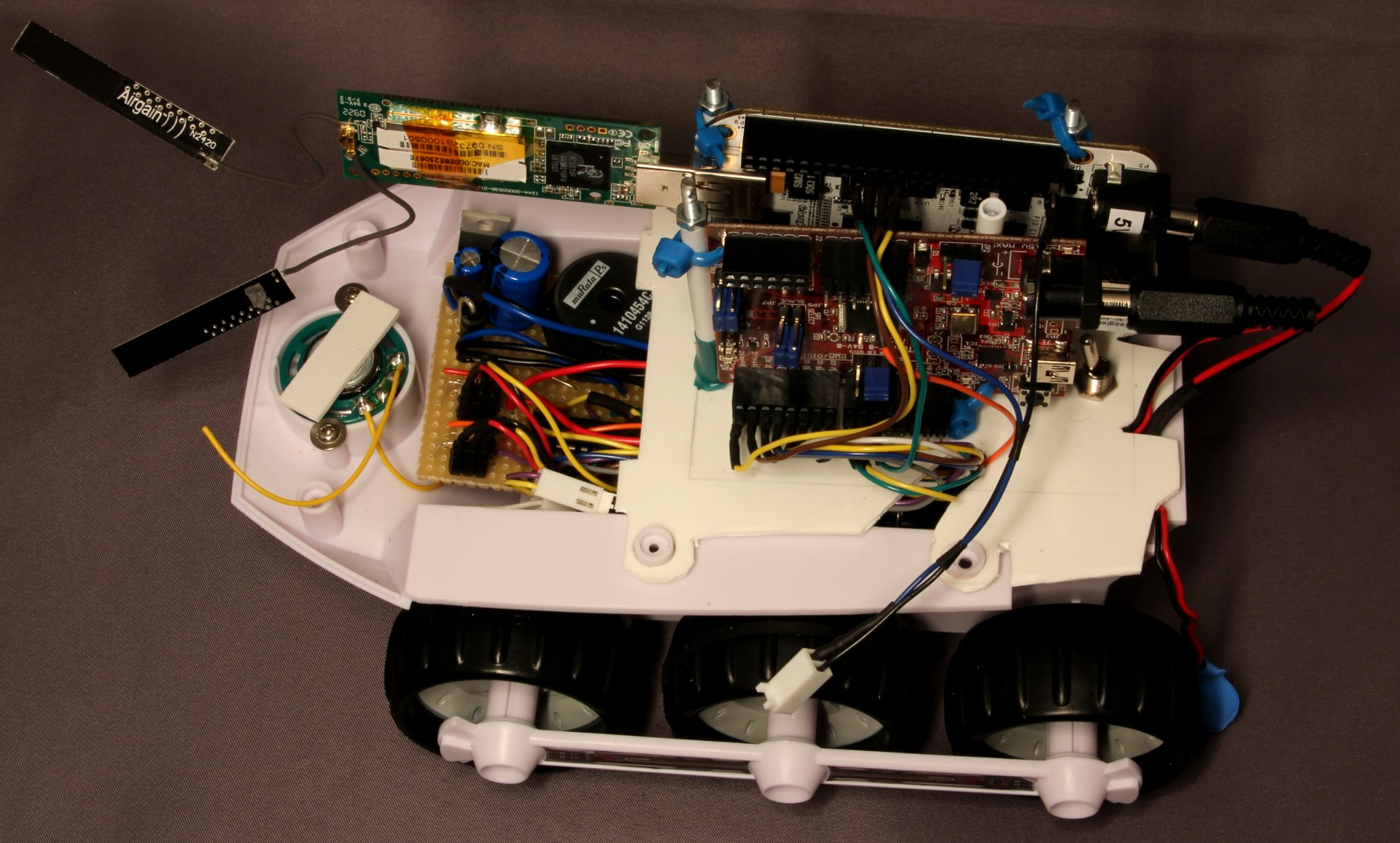
Having replaced the electronics in a BigTrak junior, I needed some way to control it from my BeagleBone. Initial experiments with driving the L293D directly from GPIO pins were quite successful but I quickly discovered the opto-encoders on the toy were extremely high resolution and needed some proper real-time interrupt based handling. Doing this from the high-level Linux based environment on the BeagleBone just sounded too much trouble to me so I looked around for something a bit lower level to handle the opto-encoder tick counting. I was torn between an Arduino Uno and the ChipKit Uno. In the end I went for the ChipKit for two reasons, the BeagleBone I/O is only 3.3V and not 5V tolerant at all. This would have meant level translators were required on any interface between the Arduino and BeagleBone, but the ChipKit is already 3.3V. The other reason was at full speed the motor encoder ticks come through about 1200 times a second, with two that means about 2500 interrupts a second. I've got no idea how big the interrupt overhead is for the Arduino but I thought if I handle 16 or 32 bit tick counters in the interrupt with that frequency it is going to get a bit close to the limits of available CPU cycles, the ChipKit is 32bit and has an 80MHz clock so plenty of time to do all I needed. The features I've used are all available on the Arduino, due to some pin function constraints you'll need to swap around the pin order a bit but the code should work okay on an Uno (provided it can keep up).
The two motors have identical interfaces to the ChipKit; two digital pins for direction control, one PWM pin for the enable line and one external interrupt for the opto encoder. The UART pins (0 and 1) are used to interface to one of the OMAP hardware serial ports on the BeagleBone. Finally a digital pin is used as a "Busy" flag which is set high once a command has been received and set low once it has been completed. This makes sure the host doesn't overflow the serial buffer and allows the host to know exactly when each command is done. The commands can take a long time to complete because of the mechanical component which is very slow compared to the digital electronics. When running there is no perceivable gap between commands even though a new one isn't sent until after the last one is finished because the processing is so fast compared to the command execution time.
In the setup code the two hardware interrupts are attached to a pair of really short functions that just increment a counter for each wheel. Note that these variables are declared as volatile at the start of the code. This tells the compiler not to cache the variable in the CPU or optimise it out, normally for example a while loop in C++ which doesn't ever change the variable it is testing e.g.
while(a < 10) {
  b++;
}
would never end because there's nothing changing variable a, so the compiler will actually optimise this out removing the "pointless" comparison. In microcontroller systems where execution can jump to an interrupt routine, or a variable can represent some hardware which changes without the code altering it the variable needs to marked as volatile so the compiler knows that something outside the normal flow of the program can change the variable.
The main loop code listens for commands then executes them before looking for the next command. It is pointless listening for commands at the same time as executing one becuase there's no way to execute more than one command at a time. The serial protocol I've defined is very simple, 8 bytes are sent, representing two 32bit signed integers which is the number of steps forward or backward for each wheel. A final byte with hex value 0xA5 is then received to start execution of the command. This extra byte makes sure that the two ends of the serial cable are in sync, without it every 8 bytes the ChipKit would try and move the wheels a number of steps which could be disasterous if there was some startup noise on the serial line that has put a couple of random bytes into the buffer first. If a sync byte is received at any time the buffer is reset even if a full 8 bytes haven't been received yet so it can be used to reset the serial interface before sending commands to make sure the two integers match up. To make sure there are no accidental reset bytes sent an escape character is defined, 0xAA. If an escape character is detected it isn't put in the receive buffer but the next byte will be even if it is a reset or escape character, so to send a 0xA5 byte in the middle of an instruction you send 0xAA then 0xA5. Similarly if a 0xAA byte is part of one of the integers it must be preceeded by an extra 0xAA. These values were chosen because of the high number of edges (0xAA is b'10101010' for example) so it's very unlikely that they could be accidentally generated by noise.
Each byte received is put into an 8 character buffer rxbuff. There are two integer pointers declared for targetA and targetB which point to the start and middle of rxbuff. Because the type of the pointer is integer (which means 32 bit signed integer on the ChipKit) the 4 bytes it points to are treated as an integer rather than a set of characters, this saves an extra variable and does away with the need to copy the values from one part of memory to another.
I found when testing that the code can't stop the motors quickly enough if they are running at full speed, the encoder ticks just go past too fast. This is easy to fix since we are using the PWM outputs to control the speed. Once the motor gets to 70% of its target number of ticks an analogWrite() command slows it down to less than half of full speed. Note that speed is not directly proportional to duty cycle. There is a dead area at the bottom end where there isn't enough power to overcome friction so although the analogWrite() command goes from 0 to 255 the actual useful band runs from something like 100 to 255, below this the motors just don't move. It would be better if the slow down happened maybe 200 ticks or 70% before the end whichever is smaller because on long runs the slow down is a long time from the target.
Like the Arduino, the ChipKIT has 1k resistors between the USB-to-serial adapter and the UART pins. This means that if you drive the pins directly from another source you'll easily overcome any drive from the inactive serial chip. I hooked the pins straight into a UART on the BeagleBone and everything worked once I had output from the BeagleBone working.
Because the onboard regulator is already providing 5V I put the powersupply jumper on the ChipKIT to "bypass". This means the onboard 5V linear regulator is doing nothing and it relies on the supply being an accurate 5V. Since the switchmode regulator is more efficient under heavier load this should be better on battery life than using the linear regulator on the ChipKIT.
| Attachment | Last Update | Size |
|---|---|---|
| ChipKit sketch | Aug. 26, 2014, 10:13 p.m. | 3.2 KB |
Comments
If you want to discuss this article you can reach me via email.